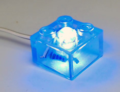
L.E.D. stand for Light Emmiting Diode.
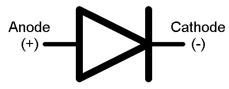
A Diode is a one-way gate in electronics; current flows in the direction of the arrow (from + to -)
If a diode is hooked up backward it doesn't allow any electricity to flow.
So an LED will only light up if it is connected the right way around.
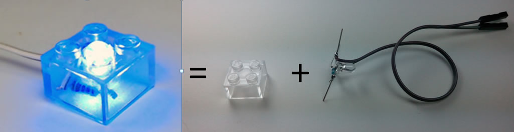
Assembly Part II - BlinkBlock
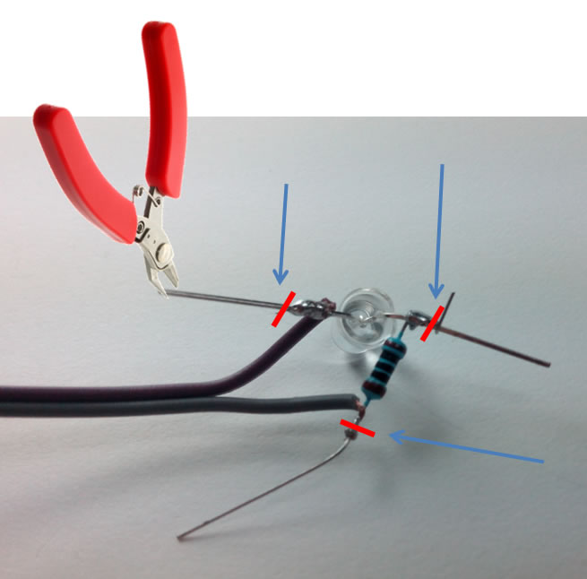
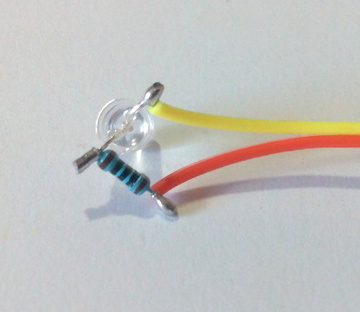
Trim the extra length off the legs
(Cut where the red marks are)
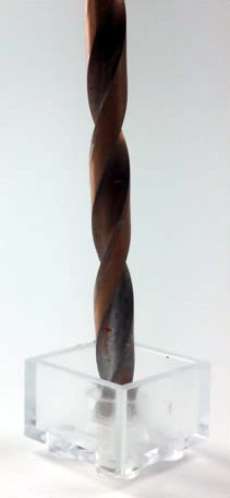
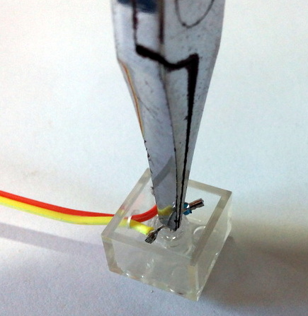
Drill a 5mm hole through the middle
(Drill with the block upside-down, like the picture)
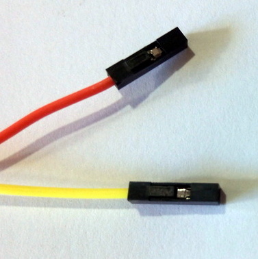
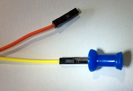
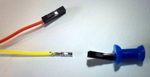
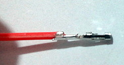
Use a pin to bend the little black plastic "tongue" up
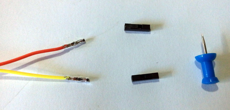
Gently slide the plastic housing off the end of the wire
Remove both of the black plastic housings from the ends of the wires
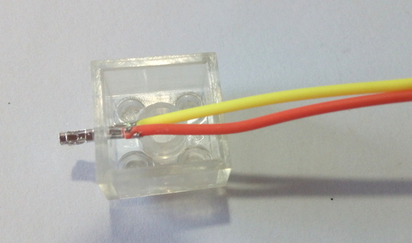
Insert the ends of the wire into the block
(From the inside of the block)
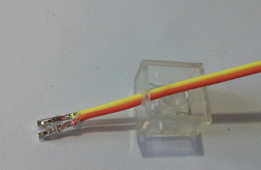
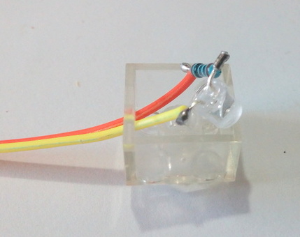
Push the wires through the hole in the side of the block
Pull the wires until the LED is almost inside the block
Use your fingers or some pliers to gently press the LED into the hole
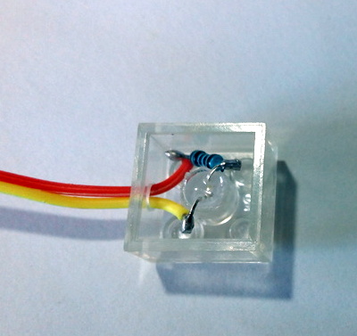
Press the resistor and legs gently down into the block You can double check that eventhing is pressed down enough by placing the BlinkBlock onto another piece of Lego and making sure they snap together all the way
Slide the wires into the new 3 pin plastic housing
One wire on each side (no wire in the middle)
Make sure you push the wires in until you hear and feel them click
Gently tug on each wire to make sure it has clicked into the housing.
Assembly Part III - Test and Glue
Test your BlinkBlock BEFORE gluing it
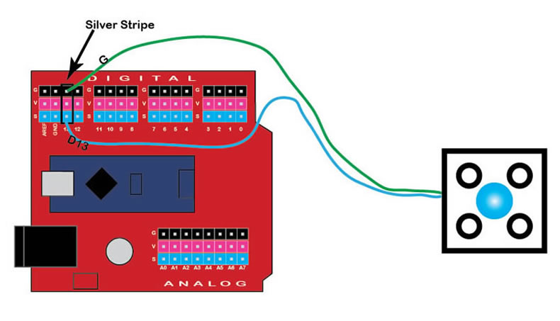
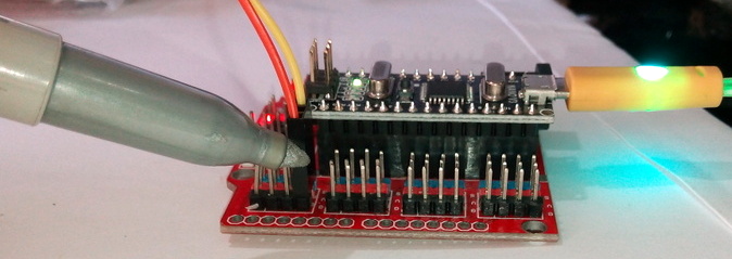
Connect your BlinkBlock to Pin 13 (on the Digital Side)
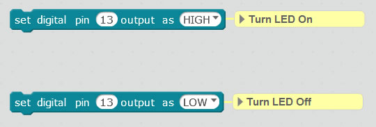
Make both of these Blocks in mBlock
(you will find them in the Robot section)
Click on the HIGH block
Your BlinkBlock should turn on
If it doesn't then try turning your connector around.
Once you know which way is the correct way for your connector
Mark the 'G' edge with a silver pen
We use silver to show Ground (the black pins)
Check with Mr. Dash before continuing
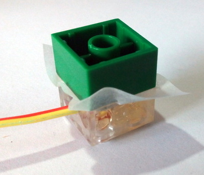
Make sure you have all the materials in the picture before gluing
(Extra Brick & Wax Paper)
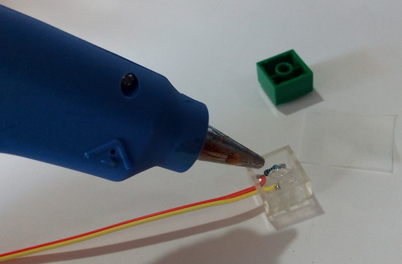
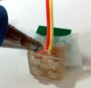
Fill your block with hot glue
Only use enough glue to cover the wires, resistor, and LED
(too much and it will squish out the sides)
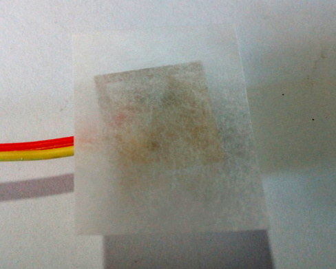
Cover the block with wax paper (baking paper)
Place another block onto your BlinkBlock
This makes sure the glue is squished down enough
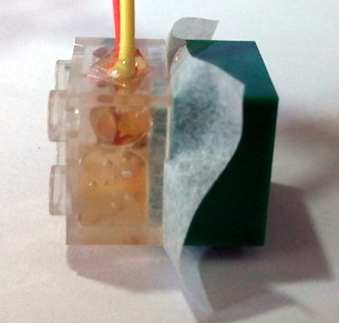
Place a little glue around the wires to protect them
Wait at least 5 minutes before removing the spare block You don't need to hold it during this time
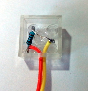
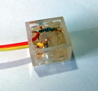
You're done!
Your BlinkBlock should look like this.
Connection Diagram
If it is connected backwards no damage is done, but it does not work.
The sliver stripe shows you which way is the right way.
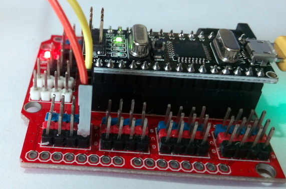
The BlinkBlock can be connected to any Digital Pin (D0 & D1 should not be used as they reserved for mBlock)
There is also built-in LED on the BrainBlock that is always connected to D13 (it is good for testing).
You should see it turn on and off with your BlinkBlock.
Example Programs
Project Ideas
Lighthouse
Dragon
Lego Pet
Traffic Light
Mini Challenges
Use 2 sprites: one to turn it on when you click on it, the other to turn it off
Create a sprite that makes it blink 10 times when you click on it
Make a Police Car (use 2 BlinkBlocks), and have its lights flash back and forth
Add a sprite that turns it on but only at 50% brightness